How to Design Parts for CNC Machining?
There are 10 points you have to note when you are designing the products to make by CNC machining.
1. Thinnest Wall Thickness
The wall thickness of the design can’t be too thin. The recommended minimum size is following:
Metal:0.8mm
Plastic:1.5mm
Studies have shown that wall thickness is proportional to the stiffness of the material, therefore lowering the wall thickness would also lower the stiffness of the material hence reducing achievable accuracy as a result of inevitable vibrations during machining.
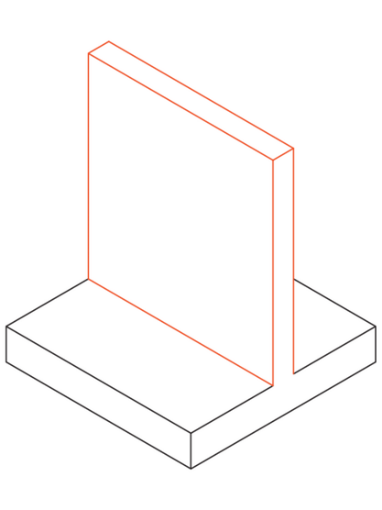
Generally, the sheet metal fabrication is the most suitable manufacturing method for the products with wall thickness less than 6mm.
2. Avoid the design that can’t be CNC machined.
Not every feature is machinable. Unnecessary elements would just make designs challenging to produce, similar to thin walls. When designing for CNC machining, having knowledge of the machine’s capabilities is frequently advantageous because it will assist you create design that the machine can produce.
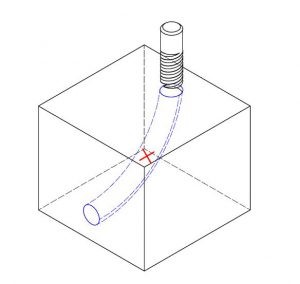
Curved holes are an illustration of a feature that is impossible to process and cannot be made by CNC mills, lathes, or drills. However, electrical discharge machining (EDM) may be employed if this characteristic is required for your design, along with additional features that are difficult to be machined.
3. Tolerance requipment
Tolerances should not be used excessively.
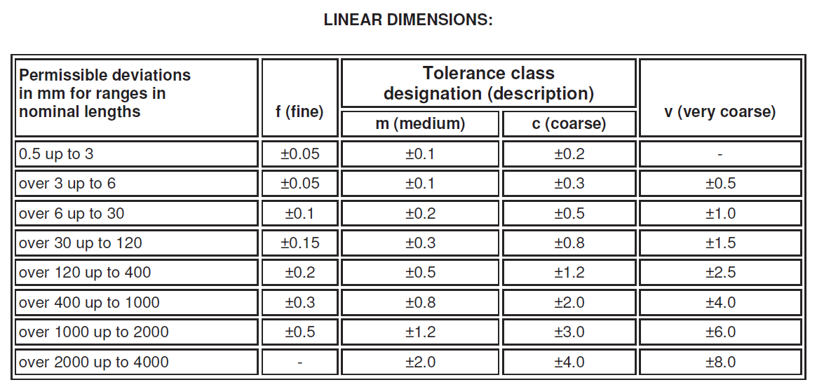
Designers are expected to allow for dimension tolerances where necessary. However, it should be noted that excessive tolerancing would only increase machining time and cost. Because different CNC machines have different tolerance standards, if your dimensions do not have tolerancing, the machine will use its standard tolerance for such dimensions. Tight tolerances should be specified only when absolutely necessary to save time and money. Maintaining homogeneous tolerancing is also important because it reduces machining time.
Tianhui tolerance standard is based on “ISO 2768-mK”.
4. Don’t design extraneous aesthetic elements.
Some features, as stated in the aforementioned ways to improve CAD designs, are only cosmetic and cannot be machined efficiently. Before removing parts for cosmetic reasons, consider the amount of material to be removed and the process to be used. As a designer, you should always ask yourself, “What process would this feature require?” or “Is it a 5-axis or a 3-axis machining process?” You can improve your design by focusing on the accuracy of necessary features rather than aesthetics, because aesthetics can be achieved through post-machining processes such as electro-polishing.
5. Create cavities that have precise depth-to-width ratios.
When designing cavities, you can improve your design by considering the depth to width ratio. Too deep cavities would result in the tool hanging, deflection, chip evacuation difficulty, and tool fracture.
Cavities should have a maximum depth of four times the cavity’s breadth and should not be higher than six times the tool’s diameter. For example, the cavity that is 15 mm wide shouldn’t be any deeper than 60 mm.
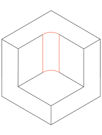
6.When designing internal edges, add radii.
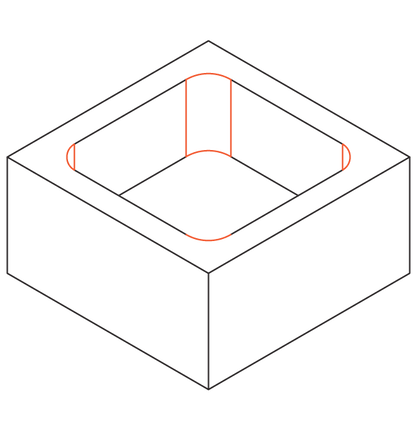
Considering the form of the milling tool, designing interior sharp edges is difficult. It is crucial to include radii to interior edges in your design because the majority of cutting tools are cylindrical and cannot machining sharp internal edges. Internal edges that don’t put the tool under excessive stress must be designed in order to prevent tool wear and tear. A decent general rule of thumb is to increase the radius by 130 percent of the milling tool radius in order to achieve this. If the radius of your milling tool is 5 mm, it is advised that you increase all of your internal angles by 6.5 mm. The tool would experience less strain and cut more quickly with the added radius.
7. Thread Length
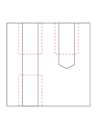
Thread minimum size is M2 ; M6 or larger recommended
The internal thread is cut with a tap, and the external thread is cut with a tool. Taps and tools can be used to cut threads to M2.
CNC thread tools are common and preferred by machinists because they limit the risk of tap breakage. CNC thread tools can be used to cut threads to M6.
8. Avoid designing features that are too small.
Because the minimum tool diameter on most CNC machines is 2.5mm, any feature smaller than 2.5mm would be difficult to machine. Too small features would necessitate the use of a special tool, increasing machine costs and time. As a result, small features should be avoided unless absolutely necessary.
9. Standard-sized holes
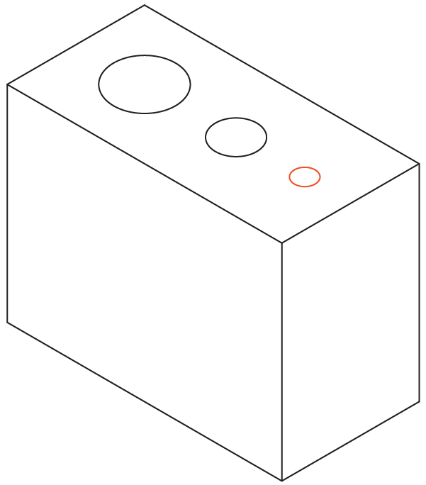
The drill diameter recommended standard size: any diameter greater than 1 mm will work.
Use a drill or end milling cutter to machine the hole. The dimensions of drill bits are standardized (metric and imperial units). Reamers and boring tools are used for finishing holes that require tight tolerances. For smaller than ⌀20 mm, standard diameter is recommended.
10. Text and lettering
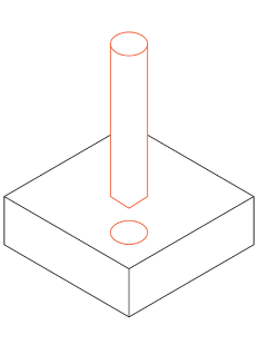
Recommended font size is 20 (or larger) with 5mm lettering.
Embossed text is preferred for engraved text because removed material is less. The sans-serif font (such as Arial or Verdana) that is at least 20px in size is recommended. Many CNC machines have pre-programmed routines for these fonts.
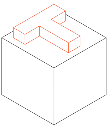
The above 10 points are very import for How to Design Parts for CNC Machining.
If you just have finished the drawings that need to be produced by CNC machining, please contact us.


Leave a Reply
Want to join the discussion?Feel free to contribute!